PRODUCT CATALOG
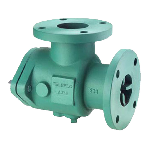
Suction Diffuser
Design Features
- Reduces installation costs by replacing the strainer, elbow, and entry pipe on the suction side of the pump
- Integral straightening vanes ensure uniform flow to the suction Inlet of the pump
- Minimal pressure drop (Oversized body & screen)
- Perforated stainless steel screen with a 20 mesh stainless steel. removable start-up sleeve to help promote a cleaner more trouble free system
- Bolted cover plate with O-ring seal – standard. (Knobs available upon request)
- Cast supporting pads on the diffuser body offer easy mounting of standard I.D. support foot
- Tapping for inlet and outlet differential connections – Optional
- Drain connection with plug – standard
- Magnetic strip on request
Applications
The Teleflo Suction diffuser mounts to the suction side of a pump in either a horizontal or vertical position. It is designed to remove any foreign matter that may be hazardous to the pump or other system components, while providing the proper flow conditions to the pump. Where space is limited, the Teleflo suction diffuser can be used as an elbow (in some cases a reducing elbow) with a built in strainer easy maintenance and system performance.
Construction
The Teleflo Suction Diffusers are constructed from rugged cast iron castings that are machined to exacting specifications. These bodies have drilled flanges that are in accordance with ASME B16.1.
Material Data
| BODY | CAST IRON, CAST STEEL, SS304, SS316, FABRICATED CS |
| SCREEN | STAINLESS STEEL (SS304, SS316), BRASS |
| MESH SLEEVE | STAINLESS STEEL (SS304, SS316), BRASS |
| COVER | CAST IRON, CAST STEEL, SS304, SS316, FABRICATED CS |
| GASKETS | CAF, NEOPRENE |
| HEX HEAD BOLT † | STEEL |
| PLUG | CAST CARBON STEEL |
| STUB | SAME AS BODY |
* Ductile Iron Knobs are available upon request.
Screen Sizes
| SIZE | SCREEN PERFORATION | OPEN AREA |
|---|---|---|
| 2” to 12” | 3/16″ | 51% |
* 20 mesh stainless steel sleeves are provided with all Suction Diffusers for start up applications.
Working Pressures - Non Shock
| NOM. RATING | MEDIA | 2” to 12” | 14” and Larger |
|---|---|---|---|
| 125# (FLANGED) | W.O.G. | 200 PSI @ 150 °F | 150 PSI @ 150 °F |
Dimensions
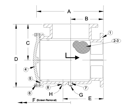
| Size (Inlet X Outlet) | A | B | C | D | E | F (Screen Removal) | G (Blow Down Connection) | H (Pipe Support I.D) | Weight (Lbs) |
|---|---|---|---|---|---|---|---|---|---|
| 2 X 1-1/2 | 10 | 4-1/2 | 4-1/2 | 7 | 6 | 8-13/16 | 3/4 | 1.02 | 24 |
| 2 X 2 | 10 | 4-1/2 | 4-1/2 | 7 | 6 | 8-13/16 | 3/4 | 1.02 | 24 |
| 2-1/2 X 2 | 10-5/8 | 5 | 5 | 7-13/16 | 6-9/16 | 9-1/8 | 3/4 | 1.02 | 27 |
| 2-1/2 X 2-1/2 | 10-5/8 | 5 | 5 | 7-13/16 | 6-9/16 | 9-1/8 | 3/4 | 1.02 | 37 |
| 3 X 2 | 10 | 4-1/2 | 5-1/2 | 8-1/8 | 6 | 9-5/8 | 3/4 | 1.30 | 42 |
| 3 X 2-1/2 | 11-3/16 | 5-1/2 | 5-1/2 | 9 | 7 | 9-5/8 | 3/4 | 1.30 | 46 |
| 3 X 3 | 11-3/16 | 5-1/2 | 5-1/2 | 9 | 7 | 9-5/8 | 3/4 | 1.30 | 51 |
| 4 X 3 | 13-1/8 | 6-1/2 | 6-1/2 | 11 | 8-.3/4 | 11-1/2 | 1 | 1.30 | 74 |
| 4 X 4 | 13 | 6-1/2 | 6-1/2 | 11 | 8-1/4 | 11-1/2 | 1 | 1.30 | 76 |
| 5 X 4 | 15-1/2 | 7-1/2 | 7-1/2 | 13 | 10 | 14-7/8 | 1 | 1.30 | 106 |
| 5 X 5 | 15-1/2 | 7-1/2 | 7-1/2 | 13-3/4 | 10 | 14-7/8 | 1 | 1.30 | 111 |
| 6 X 4 | 13-1/8 | 6-1/2 | 8 | 12-3/16 | 8-3/4 | 16-9/16 | 1 | 1.30 | 93 |
| 6 X 5 | 16-5/8 | 8 | 8 | 14-7/16 | 10-11/16 | 16-9/16 | 1 | 1.30 | 128 |
| 6 X 6 | 16-5/8 | 8 | 8 | 14-1/2 | 10-11/16 | 16-9/16 | 1 | 1.30 | 149 |
| 8 X 5 | 19-3/16 | 9 | 7-9/16 | 13-1/8 | 13 | 16-7/8 | 1 | 1.30 | 178 |
| 8 X 6 | 16-7/8 | 8 | 9 | 15-1/2 | 10-11/16 | 16-7/8 | 1 | 1.30 | 178 |
| 8 X 8 | 21-3/8 | 9 | 9 | 17-1/4 | 11-5/8 | 22-7/8 | 1-1/4 | 2.05 | 267 |
| 10 X 8 | 21-3/16 | 9 | 11 | 19-1/4 | 11-5/8 | 22-7/8 | 1-1/4 | 2.05 | 353 |
| 10 X 10 | 26-11/16 | 11 | 11 | 20-3/4 | 14-3/16 | 30-1/4 | 1-1/4 | 2.05 | 388 |
| 12 X 8 | 21-11/16 | 11 | 11 | 19-1/4 | 13-5/8 | 22-7/8 | 1-1/4 | 2.05 | 492 |
| 12 X 10 | 26-11/16 | 11 | 12 | 21-3/4 | 14-3/16 | 33 | 1-1/4 | 2.05 | 492 |
| 12 X 12 | 26-11/16 | 12 | 12 | 21-3/4 | 15-3/8 | 28-3/4 | 1-1/4 | 2.05 | 529 |
* Larger sizes available on request
Certified dimensional drawings and metric drawings available upon request.