PRODUCT CATALOG

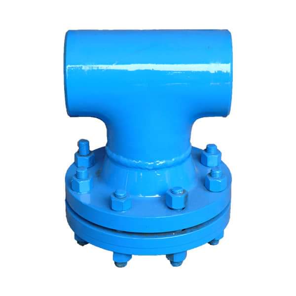
T Strainer Style A Series
Design Features
- Standard sizes from 2” – 24”. Larger sizes available upon request.
- Available with RF flanged ANSI B16.5 or Butt welded ends
- Standard thru bolt cover design.
- 304 SS perforated screens are standard.
- May be installed in horizontal or vertical pipelines.
- All welders are qualified to ASME Section IX.
- Strainers designed to meet the requirements of ASME B31.1, ASME B31.3 and / or ASME Section Viii, Div. I.
- Drains, vents, differentials and pecial covers are optional.
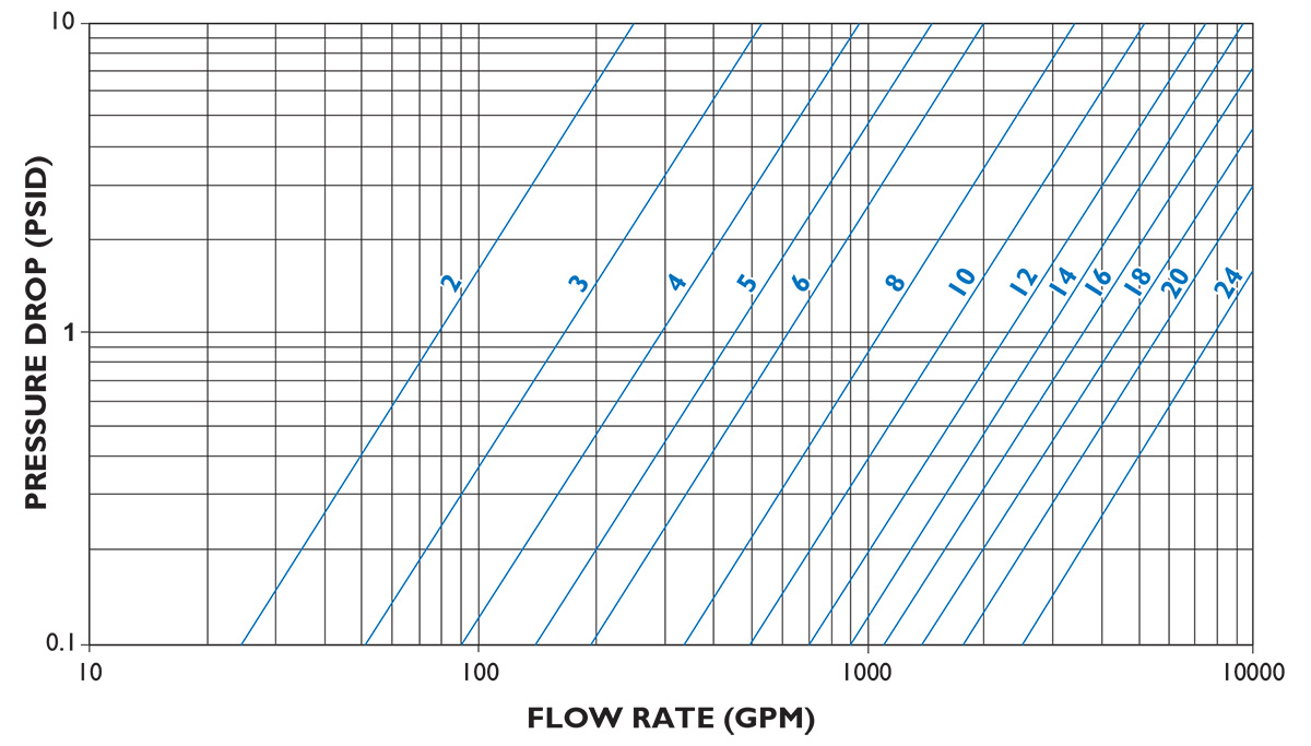
- Pressure drop as per Table-2
- End and cover flanges can be supplied as Slip on
Material Data
| Body | A234 Gr WPB/ CS TO IS1239/3589 / ASTM A106/SS304/ SS316 |
| Cover | CS TO IS 2062, ASTM A105, SA516 Gr60/70, SS304, SS316 |
| Connection Flanges | CS TO IS 2062, ASTM A105, SA516 Gr60/70, SS304, SS316 |
| Fasteners | A193 Gr B7, CS TO IS 1367, Stainless steel |
| Gaskets | Neoprene, Nitrile rubber, CAF, Teflon, SS304/316 Spiral wound |
* Other materials available on request.
Standard Screens
| Size Range | Opening | Guage Thickness |
|---|---|---|
| 2″-8″( 50mm-200mm) | 0.125 IN. (3.2mm) | 22 |
| 10″-12″(250mm-300mm) | 0.125 IN. (3.2mm) | 16 |
| 14″-24″(350mm-600mm) | 0.188 in. (4.8mm) | 11 |
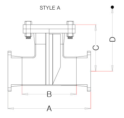
Dimensions

| Size mm |
A mm |
B mm |
C mm |
D mm |
|---|---|---|---|---|
| 50 | 254 | 127 | 146 | 279 |
| 80 | 311 | 172 | 179 | 349 |
| 100 | 362 | 210 | 205 | 413 |
| 125 | 425 | 248 | 237 | 489 |
| 150 | 464 | 286 | 257 | 540 |
| 200 | 559 | 356 | 305 | 660 |
| 250 | 635 | 432 | 348 | 762 |
| 300 | 737 | 508 | 400 | 889 |
| 350 | 813 | 559 | 441 | 991 |
| 400 | 864 | 610 | 468 | 1067 |
| 150 | 965 | 686 | 522 | 1194 |
| 500 | 1051 | 762 | 568 | 1305 |
| 600 | 1168 | 864 | 632 | 1473 |
Fabricated T Strainer Pressure Drop — Liquids (Sizes 50-600mm)

Note: Pressure drop curves are based on water flow with standard screens.
